Samsung N505 Hack
Samsung Nuon N505 Hack
1st December 2003, updated 1st December 2004- Disclaimer! This information is provided as-is, I don't guarantee it's accuracy in any way. If you're confident with a soldering iron, don't mind possibly damaging your Nuon and invalidating your warranty then you might find this page useful, otherwise caution is strongly recommended. This is not in any way a cook book, just bare bones pics and info. To carry out this hack common sense and lots of sanity checking would be required. Now, on with the fun ;-)
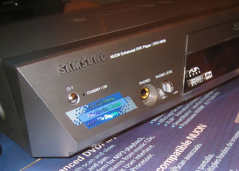
- Front of a UK Samsung N505 with a less useful sticker where the game ports would normally be.
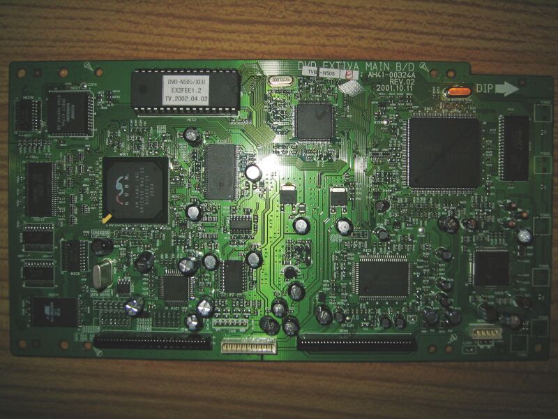
- First step, take out the main Nuon board. Begin by removing the three black screws at the rear of the machine, then remove the metal casing. Next you need to unclip the entire plastic front of the N505, which requires that you unclip the facia of the DVD tray beforehand. I ejected the tray, turned off the N505, then unhooked two clips under the tray facia. The front panel has two clips underneath, two on top connected to the drive, and one on either side. Before removing the front you need to unplug the power switch cable, and the jog dial/button cable; its fairly obvious. Now you should be able to get at the screws securing the Nuon pcb.
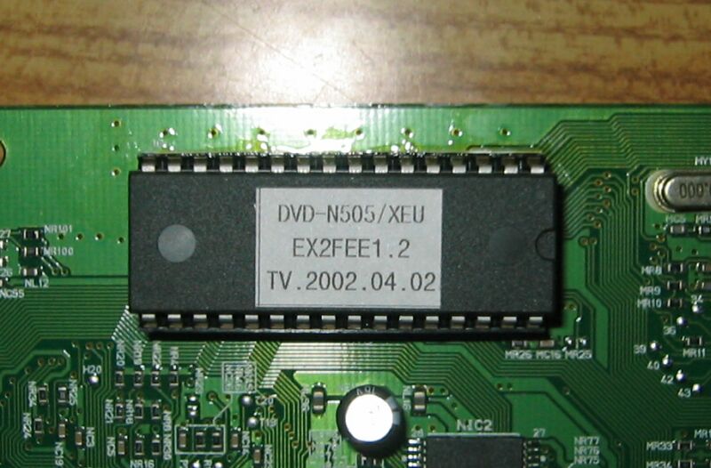
- The Nuon Bios is labelled more recently than the N505 in the pics at www.nuon-dome.com.
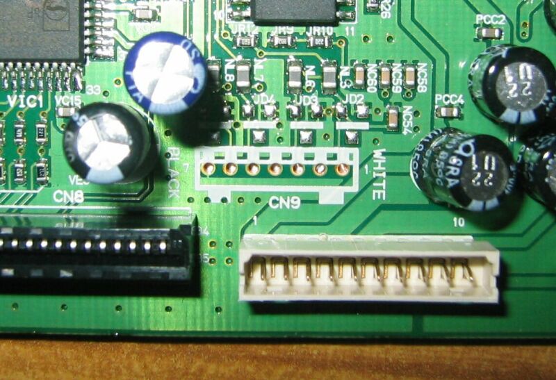
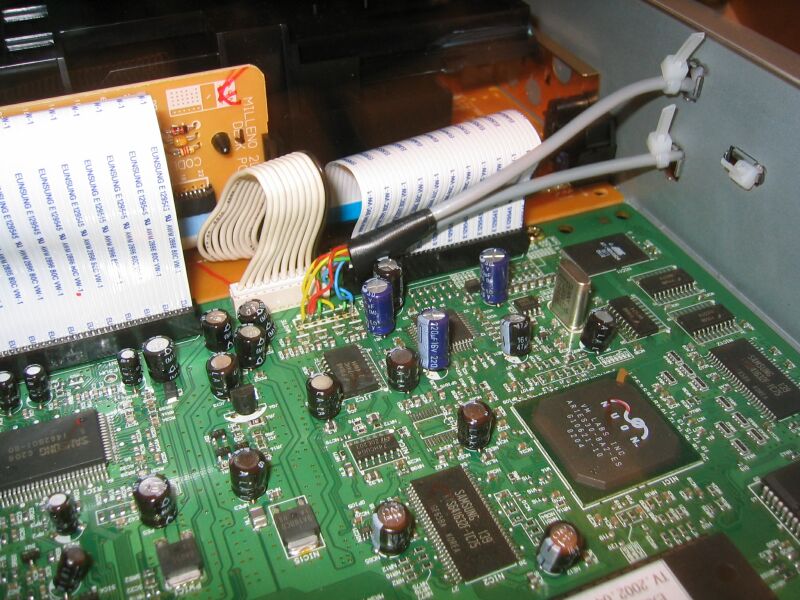
- Heres what we're after, CN9 - the controller port feed on the Nuon board. You can see its usefully labelled pins 1 - 7, which matches points 1 - 7 at JCNS1 on the small EXTIVA-JOY pcb at the front of the unit. Normally these two boards would be connected by a cable, pin to pin, 1 - 7. A bit of guess work and a few dismantled game pads later, I figured out the pin connections * note - previously I had labelled Data and Clock the wrong way around here *:
1 - Clock (Game Port 1)
2 - Vcc (approx 4V DC)
3 - Data (Game Port 1)
4 - Shield (connected to Ground on EXTIVA-JOY pcb)
5 - Clock (Game Port 2)
6 - Data (Game Port 2)
7 - Ground
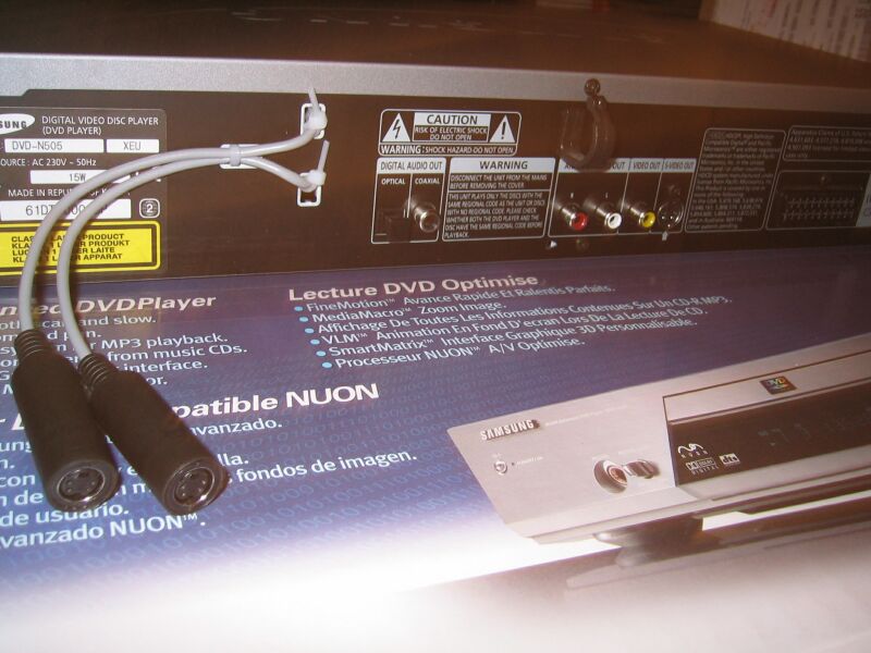
The game pads have custom 4 pin (plus shield) plugs on them that I can't get hold of, so I've decided to use 4 pin mini din plugs instead. Each game pad requires Vcc, Ground, Data and Clock, with separate Data and Clock connections for each of the two game pads. There are also five positions for signal noise filters (ceramic filters) on the small front EXTIVA-JOY pcb used for Data, Clock and Vcc. I decided to do without those, and wire up my mini din sockets straight off the Nuon board. www.rapidelectronics.co.uk do seem to have the right sort of filters in stock though. - I wanted to be able to undo these changes in the future, so instead of drilling holes I ran cables out the back of the case. My N505 had a strange mains socket cut into the back to 'store' the mains plug, so I sneaked the cable out of the case using those holes, and secured them with cable ties. Note that earlier versions of the 505 did not have this odd mains socket on the back. Mine is a N505-XEU, the one pictured at nuon-dome is marked N505-COM.
You can see from this picture that I have ignored pin 4 at CN9 on the Nuon main board, just taking whats needed. Heres how I wired up the mini din sockets:
Mini Din Socket A - Pin 1 to CN9 Pin 2 (Vcc - red)
Mini Din Socket A - Pin 2 to CN9 Pin 1 (Clock 1 - yellow)
Mini Din Socket A - Pin 3 to CN9 Pin 3 (Data 1 - green)
Mini Din Socket A - Pin 4 to CN9 Pin 7 (Ground - blue)
Mini Din Socket B - Pin 1 to CN9 Pin 2 (Vcc - red)
Mini Din Socket B - Pin 2 to CN9 Pin 5 (Clock 2 - yellow)
Mini Din Socket B - Pin 3 to CN9 Pin 6 (Data 2 - green)
Mini Din Socket B - Pin 4 to CN9 Pin 7 (Ground - blue) - View with the cables out the back, not too shabby :-)
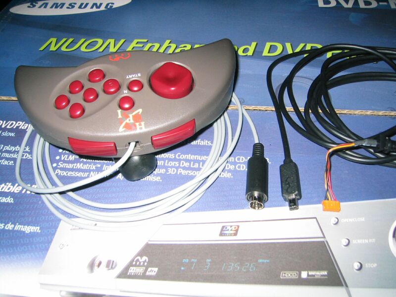
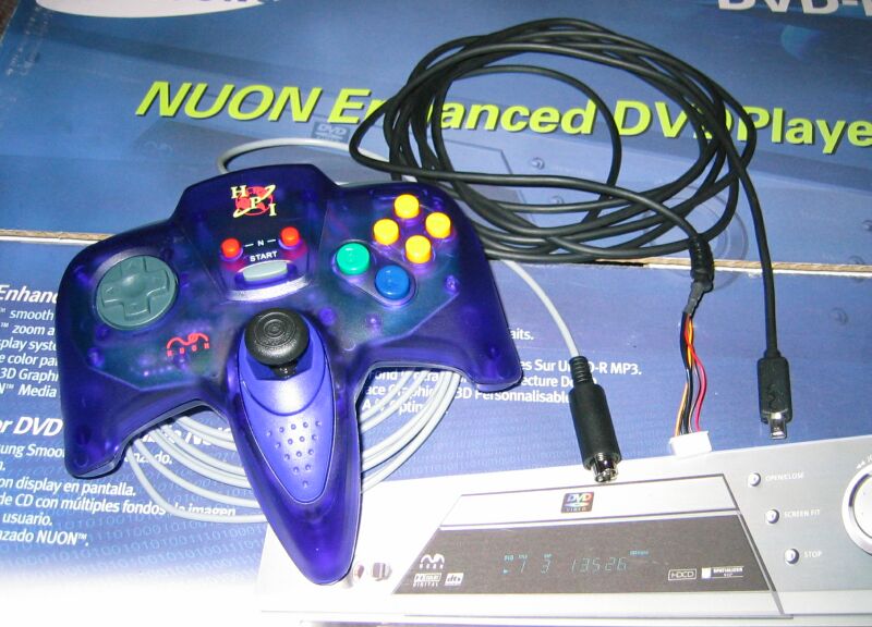
- First modded Nuon pad, with the original cable next to it. Again, I wanted to be able to undo these changes, so I left the original cable intact.
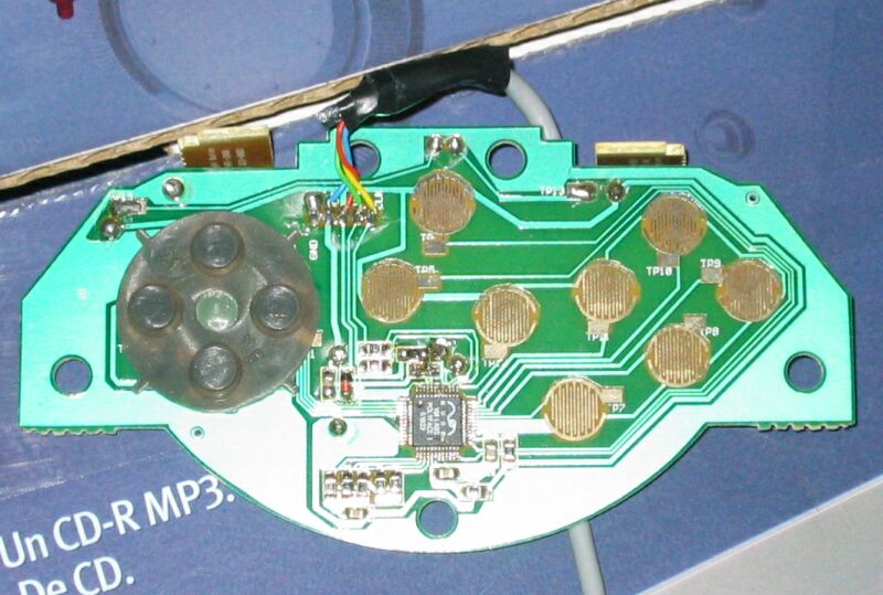
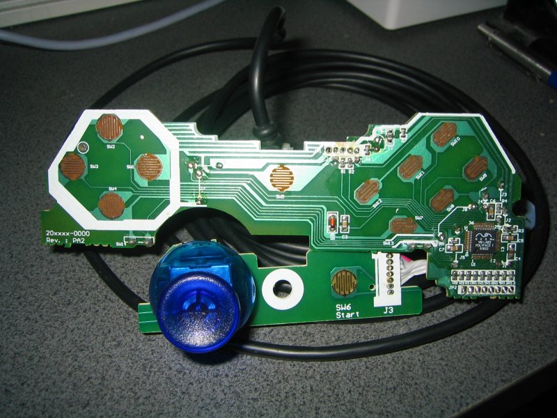
- Front of the Warrior pad pcb. The internal cable connector is labelled from left to right - SHLD, GND, VCC, DATA, CLK, so you can follow how it was wired up.
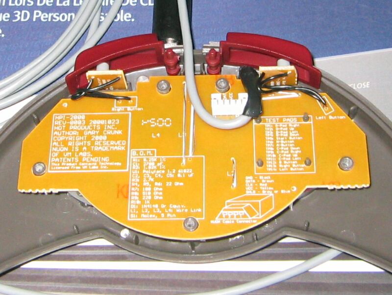
- Back of the Warrior pcb with more useful info. We have the pin numbering of the original Nuon game pad connector, and the color scheme of the original cable. Looking at the front of the Nuon game pad plug, with the Nuon logo on top (shield is wider at the base) the four pins are numbered 1 - 4 right to left. Bringing this all together:
Nuon Plug Pin 1 - Ground - Black (mine is mini din pin 4, blue)
Nuon Plug Pin 2 - Data - Brown (mine is mini din pin 3, green)
Nuon Plug Pin 3 - Clock - Red (mine is mini din pin 2, yellow)
Nuon Plug Pin 4 - Vcc - Yellow (mine is mini din pin 1, red)
Shield - Grey or Blue (it was actually black) - Modded HPI Stealth Nuon pad.
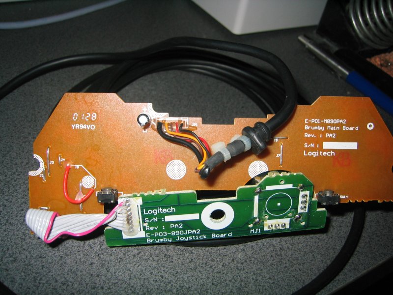
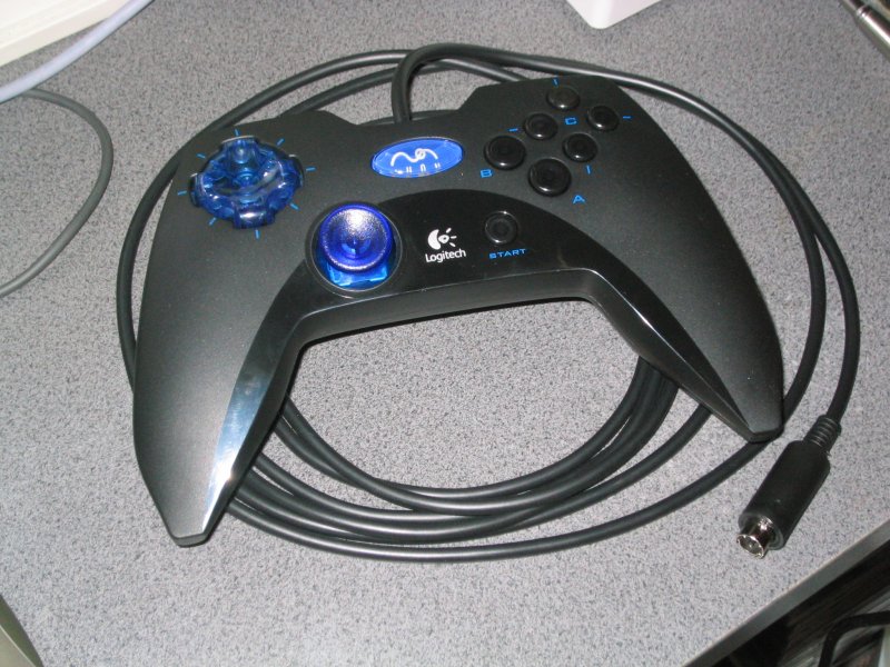
- Here are the guts of the Logitech Nuon pad, curiously nicknamed 'Brumby'.
- The rear of the Logitech pcb, wired up as follows (from left to right):
1 - Shield
2 - Vcc - Orange
3 - Clock - Brown
4 - Data - Red
5 - Gnd - Black - Completed Logitech mod.
- All of these controllers use the same micro controller internally (VM Labs Polyface 1 p/n 61822).
If you want to double check your game pad connections, this 48 pin surface mount chip can be traced to Vcc, Ground, Data and Clock. Counting the pins counter-clockwise around the chip from the dimple (bottom left of the chip):
Vcc - pins 31, 43
Ground - pins 45, 22, 23, 18, 5 - 8
Clock - pin 38 via 1 KOhm surface mount resistor
Data - pin 39 via 220 Ohm surface mount resistor - Thats it! I must thank the folks at www.nuon-dome.com and www.yakyak.org for providing enough information about all the different Nuons out there for me to try this out. In particular the guide to hacking N501 controller ports onto a N505 at www.nuon-dome.com here (go there for many more useful pics).
Also thanks to Madbury from the www.ntsc-uk.com forums for showing me the (virtual) light in the first place. Now, back to T3K and the VLM for me...
Made With Notepad
Graphics Copyright Weebl 2003
Best Viewed With Any Browser